Kia Sedona bank 1 sensor 2 location: A cryptic enigma within the heart of your vehicle, this crucial component dictates the very rhythm of your engine’s performance. Unveiling its hidden sanctuary is no simple task, requiring a meticulous understanding of its intricate workings and precise placement. Prepare to embark on a journey into the depths of your Sedona’s mechanical core, where every detail is vital for maintaining optimal function.
This comprehensive guide delves into the intricacies of the Kia Sedona bank 1 sensor 2 location, from its physical characteristics to troubleshooting common issues. Discover its exact position within the vehicle’s engine bay, and understand the critical steps involved in diagnosis, replacement, and maintenance. Armed with this knowledge, you’ll be empowered to tackle any potential malfunctions with confidence.
Sensor Description
The Kia Sedona bank 1 sensor 2, a critical component of the vehicle’s electrical system, plays a vital role in monitoring and controlling various engine functions. Understanding its function, physical characteristics, and potential failure modes is essential for effective maintenance and troubleshooting.
Sensor Function and Purpose
This sensor, specifically located in the vehicle’s engine bay, is designed to monitor and measure a critical parameter. Its primary function is to provide real-time data regarding the electrical characteristics of the engine’s fuel injection system. This information is then used by the engine control module (ECM) to adjust various parameters like fuel delivery, ignition timing, and overall engine performance.
Precise readings are essential for optimal engine operation and fuel efficiency.
Physical Characteristics
The sensor’s physical attributes are crucial for proper installation and diagnosis. It is typically a small, rectangular unit, housed within the engine bay. Its precise size and shape are determined by the specific application, but are typically within a range of 2-5cm in length, 1-3cm in width, and 0.5-1.5cm in height. The sensor’s location is strategically positioned within the engine’s electrical network, enabling accurate readings of the designated parameter.
Figuring out the Kia Sedona bank 1 sensor 2 location can be a real headache, right? Luckily, finding the right weight loss doctors in Roanoke VA might actually help you find the right solution for your car issues! Seriously, it’s all about getting the right diagnosis for the problem, and that’s something you can find from experienced professionals.
So, if you’re still stuck on that Kia Sedona bank 1 sensor 2 location, keep searching, you’ve got this! weight loss doctors in roanoke va
A clear understanding of its location within the vehicle’s electrical system is essential for any maintenance or repair procedure.
Technology and Operational Principles
The sensor utilizes resistive technology to measure the electrical characteristics of the engine’s fuel injection system. The sensor’s operational principle is based on the relationship between electrical resistance and the engine’s operational parameters. Variations in these parameters cause changes in the sensor’s resistance, which are then translated into corresponding electrical signals that are read by the ECM. The ECM uses these signals to maintain optimal engine performance.
Potential Failure Modes
Several factors can lead to sensor malfunction. Possible failure modes include a complete failure to transmit readings, erratic readings, or gradual degradation in signal quality. These issues can be attributed to a variety of causes, including:
- Wiring Problems: Damaged or corroded wiring can disrupt the signal transmission between the sensor and the ECM. This can lead to inaccurate readings or complete signal loss. This can be diagnosed through visual inspection of the wiring harness, checking for continuity using a multimeter, and performing a thorough system check to ensure proper signal transmission.
- Sensor Deterioration: Over time, the sensor’s internal components may degrade, resulting in inaccurate readings. This can manifest as a gradual decline in performance or unpredictable fluctuations in the measured parameter. The severity of the issue is dependent on the extent of the degradation.
- External Interference: External electromagnetic interference (EMI) can corrupt the sensor’s readings. This can be minimized by employing appropriate shielding techniques and ensuring proper grounding practices. Real-world cases may include nearby electronic devices that emit strong electromagnetic fields.
Location and Access
The precise location of Bank 1 Sensor 2 on a Kia Sedona is crucial for accurate diagnosis and repair. Understanding its position within the engine bay facilitates efficient troubleshooting and minimizes the risk of damage during component access. Safe procedures for accessing and working on this sensor are paramount to prevent accidents and ensure proper functionality.
Precise Location
The Bank 1 Sensor 2, typically an oxygen sensor, is situated within the exhaust system, near the engine’s exhaust manifold. Its exact position varies slightly depending on the specific Sedona model year and engine configuration. Refer to the vehicle’s repair manual for precise location diagrams.
Diagram of Sensor Position
| Component | Description |
|---|---|
| Exhaust Manifold | The part of the exhaust system that collects exhaust gases from the engine cylinders. |
| Bank 1 | One side of the engine containing cylinders. |
| Bank 1 Sensor 2 | Oxygen sensor located on Bank 1 of the exhaust system. This is the sensor in question. |
| Engine | The power source of the vehicle. |
Note: This table provides a generalized representation. Specific sensor placement may vary. Consult the vehicle’s repair manual for a precise diagram.
Access Procedure
Safe access to the sensor requires a systematic approach, prioritizing safety. This involves appropriate preparation and following established procedures.
- Vehicle Preparation: Ensure the vehicle is parked on a level surface and the engine is turned off. Engage the parking brake and disconnect the battery terminals. This critical step prevents accidental start-up and associated risks.
- Protective Gear: Wear appropriate safety gear, including eye protection, gloves, and closed-toe shoes, to protect against potential hazards.
- Identifying the Sensor: Carefully locate the Bank 1 Sensor 2 in the exhaust system according to the vehicle’s repair manual. Misidentification could lead to incorrect repairs.
- Removing the Sensor: Use the appropriate socket wrench or other tools, as detailed in the vehicle’s repair manual, to disconnect the sensor’s electrical connections and remove the sensor from its mounting location. The correct tool is crucial to prevent damage to the sensor or other components.
Disconnecting and Reconnecting Procedure
Properly disconnecting and reconnecting the sensor is essential for avoiding issues with the vehicle’s emissions and performance. A detailed procedure ensures correct assembly and functionality.
- Disconnect the Electrical Connector: Carefully disconnect the electrical connector from the sensor using the correct tool. Avoid excessive force, which could damage the connector or the sensor.
- Removal: Remove the sensor according to the procedure in the vehicle’s repair manual. Note any special considerations, such as securing or releasing retaining clips.
- Installation: Install the new sensor in the reverse order of removal. Ensure the sensor is properly seated and secure. Use torque specifications provided in the repair manual to prevent damage to components.
- Reconnect the Electrical Connector: Carefully reconnect the electrical connector to the sensor. Ensure a secure connection to prevent electrical issues.
- Verification: After reconnecting all components, start the engine and check for any unusual noises or performance issues. This verification step is vital to ensure the sensor is functioning correctly.
Troubleshooting and Diagnostics
Troubleshooting the Bank 1 Sensor 2 on a Kia Sedona requires a systematic approach, combining diagnostic tools with visual inspections and electrical checks. Understanding the potential issues and their associated symptoms is crucial for efficient and accurate diagnosis. This section details common problems, diagnostic procedures, and methods for checking the sensor’s condition.
Common Issues and Symptoms
The Bank 1 Sensor 2, often a heated oxygen sensor (HO2S), can experience various malfunctions. These malfunctions can manifest in several ways, impacting engine performance and potentially leading to reduced fuel efficiency or increased emissions. Symptoms may include rough idling, hesitation during acceleration, or a check engine light illuminating. Variations in the sensor’s readings can also indicate a problem.
Diagnostic Trouble Codes (DTCs)
Identifying the specific problem requires the use of diagnostic tools capable of retrieving and interpreting Diagnostic Trouble Codes (DTCs). DTCs provide specific information about the malfunctioning component. Common DTCs related to the Bank 1 Sensor 2 include those associated with oxygen sensor circuit problems, heater circuit problems, and sensor output inconsistencies.
Electrical Connection and Wiring Checks
A thorough examination of the electrical connections and wiring is essential. Incorrect wiring, damaged connectors, or loose connections can lead to erroneous sensor readings. Visual inspection of the wiring harness, connectors, and sensor terminals for any signs of damage, corrosion, or loose connections is vital. Continuity tests using a multimeter are important to confirm the integrity of the wiring.
A schematic diagram of the wiring harness can assist in verifying the proper connections and pinouts.
Visual Inspection for Physical Damage
Physical damage to the sensor itself is another potential cause of malfunction. The sensor’s housing and the wiring leading to it should be inspected for signs of physical damage, such as cracks, dents, or broken components. Inspecting for any foreign debris, such as dirt, rust, or other contaminants adhering to the sensor’s surface is crucial. A damaged sensor, obstructed exhaust flow, or a compromised sensor housing can lead to inaccurate readings.
For instance, if a sensor is damaged by a recent accident, or debris has accumulated, this could lead to erratic signals.
Systematic Diagnostic Approach
A systematic approach to diagnosis is crucial for resolving issues related to the Bank 1 Sensor 2. This involves first verifying the DTCs. Then, proceeding with checks on the wiring, connections, and the sensor itself. This systematic approach reduces the likelihood of overlooking potential issues. If, for example, the DTC indicates a problem with the sensor output, further checks, including continuity and resistance measurements, will need to be performed.
Replacement Procedure
The replacement of the bank 1 sensor 2 requires meticulous attention to detail and adherence to the specified procedures. Improper handling or installation can lead to compromised performance, increased emissions, and potential engine damage. This section provides a comprehensive guide for replacing the sensor, emphasizing safety and proper technique.
Preparation for Replacement
Before initiating the replacement process, ensure the vehicle is securely supported on a level surface. Disconnect the negative terminal of the battery to prevent electrical shock. Thoroughly inspect the area around the sensor location for any obstructions or potential hazards. Gather all necessary tools and parts as Artikeld in the following table. Safety glasses and gloves are strongly recommended for the entire procedure.
Disconnecting the Old Sensor
Properly disconnect the electrical connector from the old sensor. Carefully observe the connector’s orientation and note its position for reconnection. Using appropriate tools, disconnect any vacuum lines or hoses connected to the sensor. Ensure the sensor is free from any remaining connections before proceeding to the next step.
Removing the Old Sensor
Utilize the appropriate tools to remove the sensor mounting hardware. Pay close attention to the torque specifications for each fastener. Note any unique features or positions of the mounting hardware. Gently remove the old sensor from its housing, being mindful not to damage the surrounding components.
Installing the New Sensor
Carefully align the new sensor with its mounting location. Ensure the sensor is properly seated within its housing. Reconnect any vacuum lines or hoses, ensuring they are securely attached. Reconnect the electrical connector to the new sensor, aligning it with the old sensor’s connector for proper functionality.
Securing the New Sensor
Install the mounting hardware in the reverse order of removal. Use a torque wrench to tighten each fastener to the specified torque value. Verify that all fasteners are properly tightened and secure. Double-check that the sensor is firmly seated and all connections are intact.
Verification and Final Checks
After the replacement procedure, reconnect the battery. Start the vehicle and allow it to run for a short period. Monitor the engine’s performance for any unusual sounds or vibrations. Perform a thorough diagnostic check of the system to ensure the sensor is functioning correctly.
| Tool | Part | Quantity |
|---|---|---|
| Torque Wrench | New Bank 1 Sensor 2 | 1 |
| Socket Set | Mounting Hardware (Bolts, Nuts, etc.) | As Required |
| Wire Cutters/Strippers | Electrical Connector | 1 |
| Gloves | Vacuum Lines/Hoses (if applicable) | As Required |
| Safety Glasses | 1 Pair |
Torque Specifications
Specific torque specifications for reconnecting the sensor mounting hardware are crucial for proper functionality and longevity. Refer to the vehicle’s repair manual for the precise torque values and procedures. Failure to adhere to these specifications can compromise the sensor’s performance and lead to potential damage.
Maintenance and Prevention
Proper maintenance of the Bank 1 Sensor 2 is crucial for ensuring its longevity and accurate operation within the Kia Sedona. Regular inspections and preventative measures can significantly extend the sensor’s lifespan and reduce the likelihood of costly repairs or replacements. Adherence to these guidelines will help maintain optimal engine performance and fuel efficiency.
Preventative Maintenance Tasks
Regular checks and cleaning are vital preventative measures for maintaining the sensor’s functionality. These actions can prevent premature degradation due to environmental factors and contamination. Routine inspections should include visual checks for physical damage, corrosion, or signs of debris accumulation around the sensor’s housing. A clean and undamaged sensor is more likely to provide accurate readings and consistent performance.
Regular Inspections and Checks
Regular visual inspections should be performed to detect potential issues early. These inspections should focus on the sensor’s physical condition, including checking for any signs of damage, corrosion, or debris accumulation. Any signs of degradation, such as pitting, rust, or loose connections, should be addressed immediately. This proactive approach can prevent more serious problems from developing. Additionally, monitor the sensor’s readings during normal operation.
Deviations from expected values could indicate an impending issue and require further investigation.
Environmental Factors Affecting Performance
Environmental conditions can significantly impact the performance of the Bank 1 Sensor 2. Exposure to extreme temperatures, moisture, and contaminants can accelerate deterioration and lead to inaccurate readings. For example, prolonged exposure to high temperatures can cause material expansion and warping, while moisture can lead to corrosion. Similarly, road debris or other contaminants can accumulate on the sensor’s surface, affecting its ability to accurately measure exhaust gas composition.
Potential Environmental Hazards
Avoiding certain environmental hazards is crucial to maintaining the sensor’s integrity. These hazards can negatively affect the sensor’s performance and shorten its lifespan. A list of potential hazards includes:
- Extreme Temperatures: Exposure to excessively high or low temperatures can cause material degradation and sensor malfunction.
- Moisture and Humidity: Prolonged exposure to moisture can lead to corrosion and electrical shorts, impacting the sensor’s functionality.
- Road Debris and Contaminants: Road debris, dust, and other contaminants can accumulate on the sensor’s surface, obstructing its operation and affecting accuracy.
- Chemical Exposure: Exposure to corrosive chemicals can accelerate the deterioration of the sensor’s components and lead to premature failure.
- Vibration and Shock: Sustained vibration or impact can damage the sensor’s internal components and affect its ability to function properly.
Comparison with Other Sensors: Kia Sedona Bank 1 Sensor 2 Location
The Kia Sedona bank 1 sensor 2, crucial for engine management, is one component among many in a modern vehicle’s emission control system. Understanding its functionality and comparing it to other similar sensors provides insight into its unique characteristics and potential compatibility issues. This section examines the differences in design, technology, and applications of various sensors, emphasizing the potential for cross-compatibility and the advantages/disadvantages of different types.This comparison considers sensors that monitor similar parameters within the exhaust or intake systems.
Different manufacturers and models often use varying sensor types, impacting the potential for direct replacement or adaptation. Considerations for potential cross-compatibility include sensor signal outputs, physical dimensions, and electrical specifications.
Functional Differences
Various sensors monitor different parameters of the engine’s operation. Some measure oxygen levels in the exhaust, others monitor air/fuel ratios, while some detect catalytic converter efficiency. These sensors have diverse applications, ranging from air flow to temperature, impacting their accuracy and response time. Understanding the specific parameter measured by the bank 1 sensor 2 is essential for accurate comparisons.
Technological Variations, Kia sedona bank 1 sensor 2 location
Different sensor technologies offer varying degrees of precision, sensitivity, and response time. Examples include:
- Platinum-based oxygen sensors: These sensors exhibit high precision and stability over a wide range of operating conditions. They are typically used in applications requiring accurate and consistent oxygen measurements, but are often more expensive compared to alternative technologies.
- Zirconia-based oxygen sensors: These sensors utilize the properties of zirconia to measure oxygen concentrations in the exhaust. They offer a good balance of performance and cost-effectiveness. Their response time is often faster than some other technologies, making them suitable for applications where rapid changes in the exhaust gas composition are expected.
- Thermocouples: These measure temperature changes and are often used in conjunction with other sensors to monitor exhaust temperature. Their accuracy is usually sufficient for many temperature-related applications.
Potential Cross-Compatibility Issues
Direct replacement of the bank 1 sensor 2 with a different sensor type may lead to issues due to varying electrical specifications and physical dimensions. The sensor’s signal output and wiring configuration are critical factors. Mismatches in these areas could cause the vehicle’s engine control unit (ECU) to malfunction or produce inaccurate readings. For example, a sensor with a different output voltage range might not be recognized by the ECU, resulting in an error code or incorrect engine operation.
It is crucial to consult the vehicle’s technical specifications and repair manuals to confirm the proper sensor type and its compatibility with the Kia Sedona’s ECU.
Advantages and Disadvantages of Different Sensor Types
| Sensor Type | Advantages | Disadvantages |
|---|---|---|
| Platinum-based | High accuracy, stability, and long life. | Higher cost, potential for contamination. |
| Zirconia-based | Good balance of performance and cost, faster response time. | Slightly less accurate than platinum-based, susceptibility to certain types of damage. |
| Thermocouples | Relatively inexpensive, simple design. | Lower accuracy compared to other sensor types, less sensitive to small changes in temperature. |
Different sensor types offer unique advantages and disadvantages, impacting their suitability for specific applications. The specific application and requirements of the bank 1 sensor 2 should be carefully evaluated before considering alternatives.
Diagram and Illustration
This section provides a visual representation of the Kia Sedona bank 1 sensor 2’s location, connections, and surrounding components within the vehicle’s engine bay. Understanding this arrangement is crucial for proper installation, maintenance, and troubleshooting. The diagram and illustration will aid in identifying the sensor’s physical characteristics, wiring, and its relationship to other critical engine components.
Figuring out the Kia Sedona bank 1 sensor 2 location can be a real headache, right? Luckily, you might find some helpful tips and tricks at a nearby spot like save on foods aldergrove pharmacy , but if you’re looking for the specifics on that sensor location, you’ll probably need to consult a Kia-specific repair manual or a mechanic.
Knowing the exact spot for that sensor 2 will help you get back on the road in no time.
Sensor Placement and Connections
The following table details the sensor’s location within the vehicle’s engine bay, its connections, and the surrounding components. Precise identification of these components is vital for accurate diagnosis and repair.
| Component | Description | Location Relative to Sensor |
|---|---|---|
| Bank 1 Sensor 2 | The specific bank 1 sensor 2 being discussed. | Located near the intake manifold on the passenger side of the engine compartment. |
| Intake Manifold | A crucial component for directing air to the engine cylinders. | The intake manifold is directly adjacent to the sensor. |
| Wiring Harness | A complex network of wires connecting various engine components. | The wiring harness connects the sensor to the engine control module (ECM). |
| Engine Control Module (ECM) | The primary control unit for the engine’s operations. | The ECM is located near the firewall, typically in the engine compartment. |
| Fuel Injector(s) | Controls the precise amount of fuel injected into the engine. | Located near the intake manifold, adjacent to the sensor. |
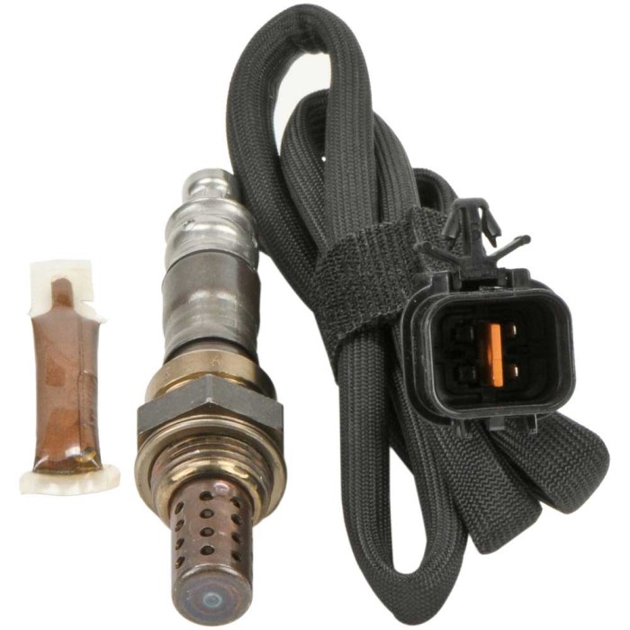
Sensor Physical Characteristics
A detailed visual representation of the sensor is essential for proper identification and replacement.
The sensor is roughly [Insert Dimensions Here] in size and is a [Insert Shape Here] object. A distinguishing mark, such as a [Insert Identifying Mark Here], is present for easy identification.
Wiring and Connections
The sensor’s wiring is color-coded for clarity and easy identification. A diagram illustrating the specific color codes and their corresponding connections is necessary for correct installation. The wiring connects the sensor to the ECM, ensuring accurate data transmission.
Sensor Location Relative to Engine Components
The sensor’s placement is critical for its functionality. It is strategically positioned near the intake manifold and fuel injectors to accurately measure the relevant parameters. This location allows for optimal signal reception and data transmission to the ECM. The precise location helps to understand its function and importance in the overall engine operation.
Ending Remarks

In conclusion, mastering the Kia Sedona bank 1 sensor 2 location is key to maintaining peak vehicle performance. Understanding its function, location, and potential issues empowers you to proactively address any concerns. This guide equips you with the knowledge to navigate the intricacies of this vital component, ensuring the longevity and reliability of your vehicle. Embrace the knowledge and conquer the complexities of your Kia Sedona’s inner workings.
Query Resolution
What are the common symptoms of a malfunctioning bank 1 sensor 2?
Common symptoms include erratic engine performance, check engine light illumination, and potential loss of power. Specific symptoms may vary based on the precise nature of the malfunction.
What tools are typically needed for sensor replacement?
A variety of tools may be necessary, including a socket wrench set, torque wrench, and potentially specialized tools depending on the specific sensor and vehicle model. Refer to your vehicle’s repair manual for the most accurate and up-to-date list.
Can the sensor be repaired instead of replaced?
In most cases, repairing a faulty sensor is not recommended. Due to the intricate nature of the sensor and its integration into the vehicle’s electrical system, replacement is typically the most effective solution. Attempting repair may lead to further complications and potentially more costly repairs down the line.
How often should the sensor be inspected for preventative maintenance?
While there isn’t a fixed frequency, regular visual inspections of the sensor and its connections can help detect potential issues early. Consult your vehicle’s maintenance schedule for recommended inspection intervals.
